
This guide is to build a wiring harness and install GTR Coils into a 2jzGE VVTi engine and utilize the factory over the coils throttle body.
Materials used to complete the project:
- R35 GTR Hitatchi Coils IGC0079 x6
- Nissan Coil Connector Kit x6
- TXL 18ga assorted colors wire (this one is my favorite)
- TXL 14ga assorted colors for power and ground
- Optional: Heat Shielding for wires
- Good heat shrink tubing
- High Temp Wire Loom
- DT 6 Pin Connector kit
- Tessa Tape
- A Coil Bracket with stalks (This is important)
Why?
Everything was running great, but one day it just started to misfire, like it went down a cylinder over 10 psi of boost and nothing i did seemed to be able to fix it. I figured I had burned up an igniter or a coil pack. Factory coil packs and ignitors are quite expensive and I thought this was a great opportunity to simplify the system.
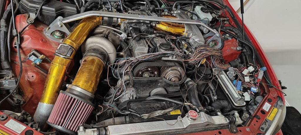
Remove Factory Coil Packs
Step 1 of course is to remove all the factory coils and wiring. I went a bit overboard and took this time to redo a lot of wiring under the hood and really clean things out. A big advantage of this system is to eliminate the ignitor. I removed all the loom from the ECU box to the engine and removed the coils, ignitor and all the wiring to the ecu to help clean up some space.
Remove Factory Parts
Step 1 of course is to remove all the factory coils and wiring. I went a bit overboard and took this time to redo a lot of wiring under the hood and really clean things out. A big advantage of this system is to eliminate the ignitor. I removed all the loom from the ECU box to the engine and removed the coils, ignitor and all the wiring to the ecu to help clean up some space.
The amount of wiring that I was able to remove from the loom was genuinely quite astounding. I was able to redo the power wire with fresh TXL 14ga going to the coil wiring harness. I happened to have some extra Summitomo pins laying around to get that completed.


Clean Up Wiring and Simplify
I also took this time to clean up the connectors in the ECU box to reduce the amount of space they take up. since they do not have to be weather proof, I was able to utilize mini-molex connectors in place of the large Summitomo/Tyco connectors. I was also able to combine two connectors into 1 connector.
One of these connectors ended up being an H connector, I learned this the hard way and I had to splice some wires together to get it all to work right, but in the end it all came together. All sorts of weird things started happening, gauges went haywire, other things quit working. It took a second and a multimeter to figure it out, but a few spliced wires together fixed the issues.
Routing the Coil power wire from the factory connector in the ecu box to the back of the head using the same path as the injector and Cam Sensor Wires. by the firewall I used a DT 2 pin harness for the power and Ground. The ground, also 14ga, is just on a ring terminal to a lug on the head. now that the power and ground wires are in place, I started to mount the coil brackets.
Coil Installation
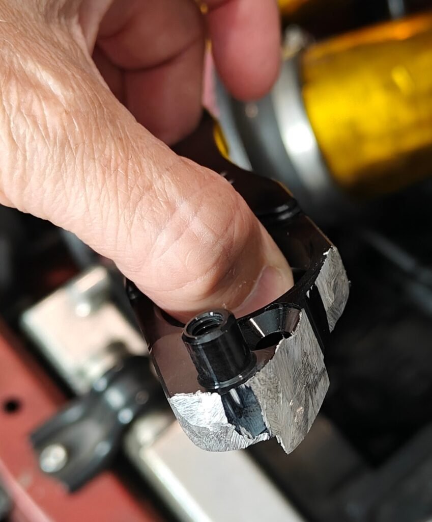
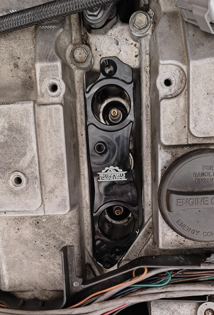
The coil brackets that I purchased (same as listed above) did need to be ground down on the very front of the engine to clear the VVTi stuff in the valve cover. The bolt to secure the bracket in place also needed to have some material removed to fit in, but it was not that big of a deal and in the end all went together perfectly. You might think this is terrible to pay then have to modify, I did send the company a message with these images to get it fixed. The biggest advantage to going with someone like this is the custom stalks that are available, this made all the difference in the installation process.
Once tested in place, I took one of the other brackets to begin creating my wiring harness in comfort, on my couch.
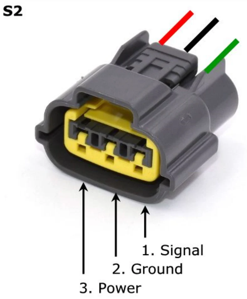
Making the wiring harness is a little tedious but also, to me, very rewarding. Utilizing one of the sections of coil brackets I have the spacing of the coils. The first one was the easiest, #1 coil going toward #6, straight build the connector using your favorite terminal crimper and a good amount of signal, power and ground wire. Here is the pinout:
Once tested in place, I took one of the other brackets to begin creating my wiring harness in comfort, on my couch.
Making the wiring harness is a little tedious but also, to me, very rewarding. Utilizing one of the sections of coil brackets I have the spacing of the coils. The first one was the easiest, #1 coil going toward #6, straight build the connector using your favorite terminal crimper and a good amount of signal, power and ground wire. Here is the pinout:
Wiring Harness
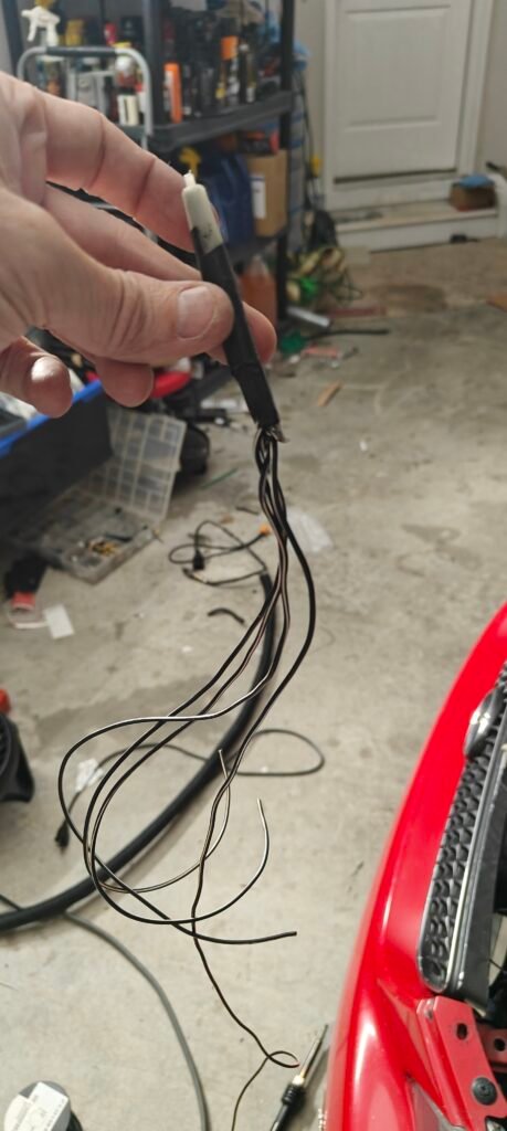
Put 2 coils into the bracket, connect coil 1 to your single made connector, keep the wire tight follow the wires to where they would connect without creating too much slack or to much of a bend. The signal wires will always remain in-tact all the way to a connector or the ecu. But the power and ground can be carefully spliced. The coils fire and charge at different times so the single wire isn’t necessarily overloaded. The 14ga power and ground are indeed a bit overkill, most of the aftermarket purchased wiring harness I found were all made from 18ga wire for all with a 8 pin connector (spliced power and grounds).
Carefully remove a small amount of the power and ground jacket and crimped in the 2nd coil’s power and ground wires then followed up with some solder and finally heat shrink. During this process do not forget to utilize your wire loom and heat shrink breaks in the loom as necessary.
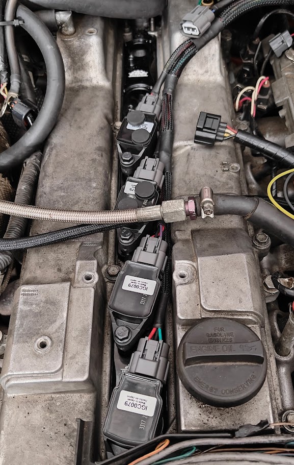
Once the first 2 connectors are completed, move the 2nd connector to the first coil and do the same for the third connector. Repeat this process until you have all 6 coil connectors and 6 loose signal wire (ideally different colors) and 1 power and 1 ground wire. The picture is mid process testing how it all fits but you can see the looming and the process while only using 2 coils in one of the brackets.
Once completed install all your brackets, then assemble the Coils with the new stalks. Now is a great time to replace your spark plugs with that nice big gap for your sweet new coils. Install the coils into place in the new brackets and install your wiring harness. I did the extra heat shielding for a few reasons, it is not necessary. Now make your connectors to length for power and ground, as well as all your signal wires.
ECU Programming & Sequential Ignition
Once completed install all your brackets, then assemble the Coils with the new stalks. Now is a great time to replace your spark plugs with that nice big gap for your sweet new coils. Install the coils into place in the new brackets and install your wiring harness. I did the extra heat shielding for a few reasons, it is not necessary. now make your connectors to length for power and ground, as well as all your signal wires.
On the Standalone ecu, you need to run wires for your 6 coils. You should at least have 3 wired in, but you can fish them out to bring to the connector. I would suggest going in order, 1->6 for the coils and the wiring, this will matter when it comes to programming.
If you don’t want to program anything you can still run wasted spark utilizing your existing 3 coil wires. But there is a catch to this, the factory IGN1,IGN2,IGN3 are not meant for coils 1,2,3 but seemingly random. Here are the teeth associated with the ignition firing for AEM EMS v2:
- Coil 1 – Ph 12
- Coil 2 – Ph 4
- Coil 3 – Ph 20
- Coil 4 – Ph 8
- Coil 5 – Ph 16
- Coil 6 – Ph 0

If you want to run wasted spark you need to wire it in as such, keep in mind that the pairings are 1&6, 2&5, and 3&4. This was you can splice wires in. I made this wasted spark harness trying to solve some issues we will get into in Troubleshooting.

Troubleshooting
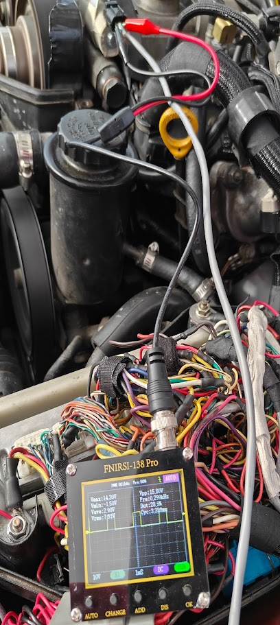
If you end up getting horrible misfires above 2000 RPM, do not freak out! Here is where my hard work and loss of mental stability will help you! I had this issue and it was certainly a weird one. Eventually I tracked it down to the ECU loosing stat-sync, I believe due to the electrical noise.

You can see the cam timing completely takes a dump, I at first thought the VVTi solenoid was freaking out, just turns out the cam sensor was losing sync.
Electrical Noise and Shielding
Here’s where I went hog wild and tore everything back apart and shielded everything I could find including the coil stalks. I got an EMF meter and spent a ton of time shielding and it did absolutely nothing. Interesting note, everything worked great with VVTi solenoid unplugged. I added layers of shielding to already shielded wires, even tried to faraday cage half the harness away from the high energy coils. When that didn’t work I ended up replacing the Crank sensor, and added shielding for good measure. I even borrowed a book from the Electrical Engineering group at work to learn more about electronic noise and shielding


Of course none of this worked. The crank signal still was weird and wonky. So now I decided to look into how the ecu was handling the crank and cam signals. I altered the min max voltage and I eventually got to a point where it wouldn’t run at all. This avenue was a bust too. I decided maybe to try wasted spark in a last ditch effort, also to no avail. The only solution to the problem that I could find was to run without VVti, and this wasn’t acceptable.
My next thought was to switch over to hall effect over Variable reluctance cam and crank sensors, this has it’s own set of problems and went against my dream of all factory Items functioning. But it led me down the road of signal conditioning circuitry. The more research I did the more i learned of people having similar issues. I happen to have some friends over at DIY Autotune and they mentioned using inline resistors on both, they specified 100k Ohm. The car never started or ran with this, so I decided to start reducing the values of resistance until it did start and eventually run consistently. With all of this experimentation going on, I decided to utilize a small breadboard to reduce any sort of destructive testing. I made some connectors from mini-Molex I had laying around to the bread board and started making circuits.
The Solution
It finally worked with one simple 1.2kOhm resistor inline for both cam and crank signals. Yes I did in fact drive the car utilizing a bread board (sort of made all my shielding efforts seem silly). The car ran perfect, VVTI functioned, no dropped signals, no misfires, all was right with the world.

I was finally able to wrap everything up, and put it all away. The good news is that EVERYTHING is shielded from an EMP attack in that car now.
I buttoned it all up and cleaned up the wires with some nice wire loom, ditching the old factory rubber stuff. I Re-routed the standalone harness around the fender well instead of over it. Enjoyed the view of no ignitor or HKS twin spark, or fuel pump resistor (another how-to thread). Made some “Goooooooooold” jokes from Austin Powers and moved on with life.
No on to the next issue of installing the factory Throttle.


Factory Throttle Installation
The factory throttle installed fin over the coils but it was incredibly close. One of the best advantages of going with the r35 coil is that they are incredibly heat tolerant and can take being crammed in to tight spaces. There was one piece of the throttle body that was resting on the coils. I chose initially to utilize some silicon pads on the coil to reduce the friction and rub of the throttle, also did my best to try and lift the throttle with silicon spacers on the valve cover.
Researching the Dodo racing coil upgrade, claims of running using the factory throttle, I did all the same throttle modifications they recommended which opened up some space, but not quite what I was looking for. the other aspect that I was fighting was the strut tower bar was a constraint on the top of the engine.
The throttle has lots of ribs and protrusions I am sure for mounting all sort of things to it in other applications. I decided to get a bit crazy and start grinding off some of these protrusions that were interfering with the coils. I also did a little bit off the top to ensure the throttle did not rattle on the strut tower bar. This was a little grinding and testing to see where more needed to be taken off or i could keep moving on.
I am still working on a solution to create a throttle seat much like the factory rest, but slimmer and perhaps a bit more solid. My fear here is the heat transfer and its ability to flex away from the engine, the point of the rubber gasket before the plenum. I have been running the car with the throttle like this for nearly a year and have not had any issues to mention. With this in mind; I cleaned up all my tools, buttoned up the remaining wiring and hardware issues and closed the hood! Great success, haven’t had a misfire since.
The car drove like stock, zero Check Engine light from the swap thanks to a P1300 simulator installed years prior, and all gauges work great. This was a complete drop in project that completely fit the bill of my ultimate vision for the car.


