
Making a CAN Gauge
Problem Statement
I have had my car the way it was for a very long time, just the architecture of the electronics. Stock ECU in piggyback with an aftermarket standalone ecu, shared signals from some sensors and added other sensors. This worked pretty darn well for a very long time. I switched to a new EMS (AEM EMS series 1 and then 2 to EMU Black) with a completely new tuning strategy that is Volumetric Efficiency. I could no longer tune my way around weird sensor readings and I needed to start making sensor signals more stable and accurate.
Another aspect of all of this was a buildup of devices that barely served a purpose or were just outdated in general. Namely my HKS EVC 5 and my standalone wideband controller, an Innovate Motorsports LC2. I utilized an XD16 as my main display for the wideband and an analog out for the EMS to read. This proved tricky as the there was a significant voltage offset I needed to overcome in the EMS to make it work. The HKS EVC had become nothing more than an ornamental piece in the car and a boost gauge. It quit functioning as a boost controller many many years ago, but it had been cut and molded into the dash so long ago i was very unwilling to do anything about it.
One element that I always wanted to learn about was fuel temperature, the easiest way to get this information is through a Ethanol sensor, it does both Ethanol content and Temperature. This of course led me to want to do flex fuel as well, because, why not.
I wanted to move away from the external wideband, but I want to keep the display. I want to get rid of the HKS, but I want to keep the display. I want flex fuel (that’s just pure addition). SOLUTION: make a display for this information and get rid of the systems.
Plan and Solutions
I needed to completely redo the fuel return line (this ended up being a better idea that I ever thought) with 30R9 line, the line going to the engine is already braided and nice, and easier to replace. I also had to put the Flex Fuel sensor inline on the return line.
I needed to utilize the built in Wideband controller in the EMU black to no longer need the LC-2.
I need to Build an arduino CAN gauge to display the information that I didn’t want to lose.
I need to remove and clean up all the old wiring and junk under the dash that has accumulated over the years.
Fuel Return and Flex Fuel
I ended up flipflopping on my fuel return quite a bit more than i should have. For whatever reason i was hell bent on using 5/16″ line and in the end i just did 3/8″. I ordered a ton of 3/8″ 30R9 fuel hose, a couple of quick disconnect fittings for the Ethanol sensor, and a push lock -6 for the fuel pump hanger bulkhead. I utilized my already existing Tomei fuel pressure regulator, replumbed everything with the new line and put the flex fuel sensor in line against the body of the car right by the bellhousing. I utilized quick disconnect fittings all so that if i need to remove the engine, it would be easy. Wiring the sensor was more of a pain than plumbing. It is a 12v sensor, not +5v, so i need to either find a +12v source or run one. I ended up finding one, the IS300 has an ACIS system that i have since deleted, but it happened to run on 12v. I did have the actuator plugged in to prevent a cel, but I installed an inline resistor and utilized the +12v and grounded it to the intake manifold. i ran the signal wire to utilize the last pin of the 12 pin DT connector for the engine harness to make sure everything is still a quick remove event if i need to pull the engine.
- Flex Fuel Sensor wiring Pigtail
- 30R9 fuel hose
- 3/8″ Quick Disconnect fittings for the sensor
- Flex Fuel Sensor
- -6AN fitting


Wideband O2
This was interesting in that I had a lot of options. I chose to utilize the O2 heater wire from the factory, I also rewired the o2 sensor that is still being utilized to extend the wiring. I am utilizing a Bosch LSU 4.9 and the wiring kits were all way more than I wanted to spend, so i just bought a plug and pin kit and utilized the wire I already have on hand (all TXL wire) to make a new harness that extends all the way to the EMU black. There are 5 wires that need to go to the EMU and 1 wire that remained in the engine bay to connect the heater power. I loomed it all up, pined my sensor and made a stupid long pigtail expecting to cut most of it, but i never did. I routed into the cabin the same path as the LC2, and ran it parallel for testing. It worked great, cool, but i want to make sure i get the gauge at least tested functional before removing the LC2 and XD16.
Supplies that I needed to purchase:

CAN Gauge
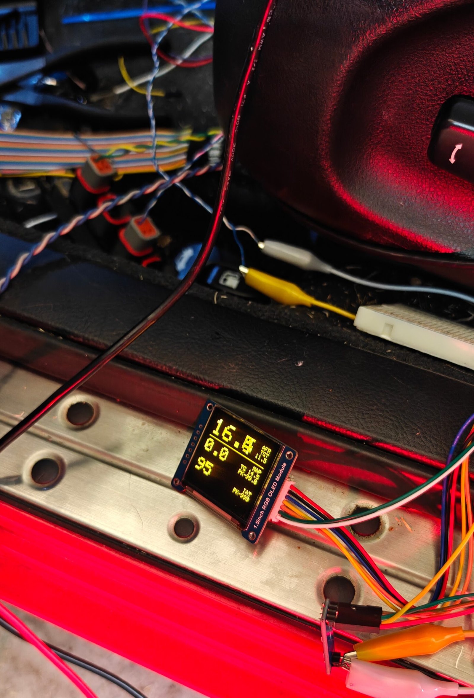
Here is the real point of all this, I needed a gauge to replace the XD16, the HKS EVC5 and any other additional things i could get out of it, super cool. I did some research and there are a bunch of libraries for Arduino to get CAN data out of the EMU, awesome, i want to mount it to the gauge cluster, surface, much like my old XD16. Needs small packaging, more research, screens are overwhelming in choices, tiny micro controllers have tons of options, then all the added things to go onto it. Very overwhelming but i started researching other project and how it all worked. I actually went with an esp32 microcontroller and and CAN chip, paired to a 1.5″ square RGB OLED display. I pulled my hair out trying to get this to work, it would not send a return signal to clear the CAN error in the EMU. I was very close to giving up. I tried to also utilize serial data, also no dice. what i learned: you need the CAN transceiver to be +5v minimum, and the ESP32 doesn’t like +5v in the RX pin, so it can go a bit haywire. I figured this out using a voltage divider and the whole thing sprang to life! Ultimately i decided to go a different rout and use a Feather M4 CAN microcontroller to simplify the setup, but everything else the same.
This is the complete shopping list outside of wire and tools. Eventually i got it working through the CAN system on it’s own power through the buck converter:
The programming is a whole different story, and many github repositories and AI chats were utilized. In the end i greenlighted the removal of all the crap I now no longer needed.
The Removal
Not really much to say here… I removed all the crap. I took this photo mid way through, I removed even more than this before it was all said and done, and I can probably keep going:

CAN Bus System
This is a basic system covered a lot in other places, but where I will add, is that it is all just wires in the end, like a basic network using RX and TX. Think of it as a big USB hub for cars and generic information. Where I will chime in for sure: you do not need a can bus block, but they are cool. I recommend not using a big boy can bus block, and get a generic one for DTM connectors. I would actually like to make one using Molex Minifit, but that is a project for another day. Here is what I bought: WildaTech Works and it was much cheaper than anything else I ever saw and the same thing. I got the cool red accent, then stuffed the block under the dash never to be seen again.
Remaining
- Design backing to the gauge
- Print all casings in ASA
- fully assemble everything and glue things into place
- mount gauge, run wires
- fix the power outlet under the armrest
- replace interior panels
- Drive and test everything
- Look into custom can messages so i can get
- Short term Fuel Trim
- Fuel Temp
- VVTi Angle/Target
- test drive the hell out of it
- enjoy delicious beverage

